Flex PCBs Can Be Used in Automotive Tactile Sensors
A flex sensor is a mechatronic system that integrates a rigid printed circuit board (PCB) with flexible components to enable dynamic bending and stretching. The resulting tactile PCB is capable of capturing pressure information from free-form surfaces, making it ideal for use in automotive applications.
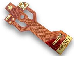
A typical flex circuit is made up of a flexible, thin substrate that’s covered in coverlay and filled with copper traces. The conductive materials are then etched into multiple layers, which are then capped with the coverlay to protect them from contaminants during manufacture. This layer stack is then laminated to a rigid backboard, where the copper traces are exposed through holes.
The resulting flexible PCB has the same electrical connections as any other PCB, but it can be bent and stretched to a variety of positions. This flexibility is critical for tactile sensors, as the pressure applied to a free-form surface can vary greatly from one position to the next. Using a flex PCB can help designers create more accurate sensors by reducing the amount of time the circuit needs to be in contact with a surface.
How Flex PCBs Can Be Used in Automotive Tactile Sensors
Using a flex PCB in a tactile sensor also provides many other benefits that can save space and money in the final product. By removing the need for traditional wiring harnesses or ribbon connectors, these sensors can be designed to fit smaller spaces and more compactly shaped products. flex pcbs also allow for a reduction in the weight of the device, thanks to their incredibly thin substrates and low material density.
There are two basic types of flex PCBs: single-layer and multi-layer. A flex-rigid hybrid board can also be used, which is a combination of both rigid and flex sections that are then laminated together.
Rigid-flex circuit boards are typically more complex than flex-only designs, but they offer the best of both worlds by offering the rigidity of a conventional PCB with the flexibility of a flex-PCB. Depending on the design, a flex-rigid PCB can be produced in either single- or double-sided, with or without plated through holes.
It’s important to know your flex classification before you begin designing. Different classes are suited to specific applications and manufacturing processes, so choosing the right class for your design can make a big difference in cost and performance.
PI and PET films are common substrates for single-layer flex circuits, while glass fiber and epoxy substrates are often used for multi-layer flex-circuits. The flex-circuits are typically pre-laminated with an insulating film to prevent copper from scratching or damaging the surface of the coverlay during manufacturing.
Copper is notorious for work-hardening and fatigue, especially in flex circuits that experience repeated bending or movement. To reduce these issues, higher-grade rolled annealed (RA) copper foils can be used. This enables the copper to stretch more before fatigue cracking occurs and makes it springier in the z deflection direction, which is important for flex-circuits that will be bending and flexing all the time.
With Altium Designer + Altium 365, you can easily select and specify the right flex-pcb materials and prepare fabrication drawings for production. Whether you’re creating a simple prototype or complex assembly, all the advanced CAD features and automated drawing tools you need to get the job done are right at your fingertips with the industry’s most trusted PCB design software. Get started with a free trial today.